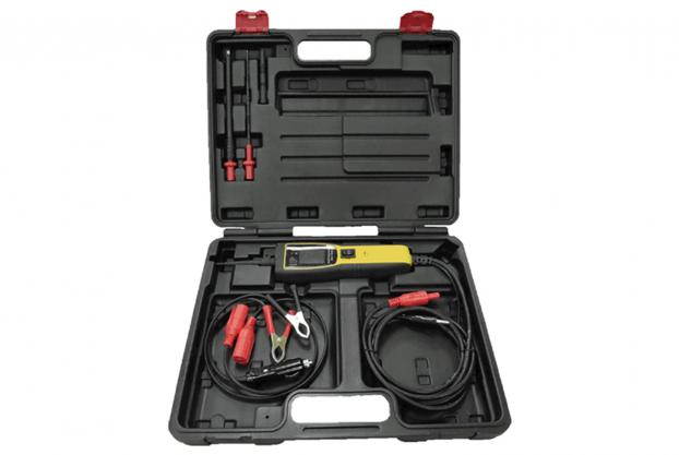
Battery & Electric System
113-6520
• 1. DC Voltage Measurement. 2. Current Measurement. 3. Resistance Measurement.
4. Signal Frequency and Max / Min Voltage Measurement. 5. Illumination.
6. Testing Power Providing.
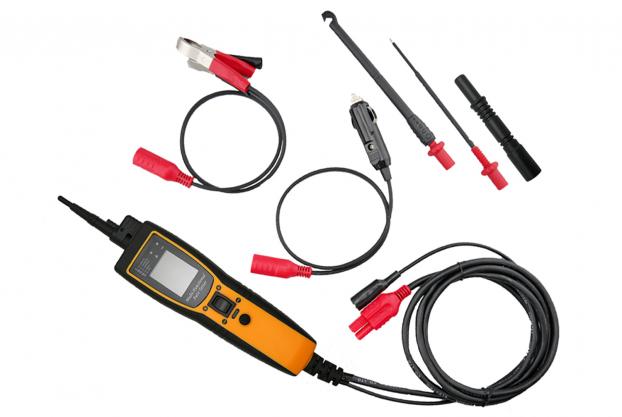
• Accessory: 1.) Power Clips. 2.) Cigarette Lighter Plug. 3.) Auxiliary Ground Connector.
4.) Connector. 5.) Long Testing Probe. 6.) Wire Piercing Probe.
• Supply Voltage: 8-30V DC. Voltage Measurement Range: 0-70V.
• DC Current Measurement Range: 0-5A DC.
• Frequancy Measurement Range: 0-300KHz (Square Wave).
• Resistance Measurement Range: 0-200KΩ. Working Temperature: 0-50°C.
• Storage Temperature: -10-60°C. Working Humidity: ≤ 85%
• Measured Temperature Range: 5-200°C / 41-392°F (The display will appear
ERROR when tester is not connected with temperature probe.)
• DC Voltage: 0-70V ± (2% + 3). Signal Frequency: 0-300KHz ± (3% + 3).
Resistance: 0-200K ± (5% + 3).
• DC Current: 0-5A ± (3% + 3). Temperature: 5-200°C / 41-392°F ± 1.5% + 5.
• Shortly press MODE button to switch function between DC voltage,
signal measurement, resistance and DC current. Connect the red clip
to positive of battery and black clip to negative of battery.
• Auxiliary ground connector is used to connect with the negative of testing
object when it is necessary.
• DC Voltage Measurement: 1.) Shortly press MODE button to switch the
function to DC voltage measurement. 2.) Connect the testing probe and
auxiliary ground connector to the two polarity of the testing object.
CAUTION: DO NOT press the POWER PROVIDING SWITCH during the
measurement. 3.) Read the voltage value from the screen.
• SIGNAL FREQUENCY and MAX / MIN VOLTAGE MEASUREMENT:
1.) Shortly press MODE button to switch the function to signal measurement.
2.) Connect the testing probe and auxiliary ground connector to the two side
of the testing target; probe to the positive and auxiliary ground connector
to the negative.
3.) Read the value from the screen.
• Resistance Measurement:---
1.) In order to prevent electrical hazard, please disconnect the power
connection and make sure all capacitor has been discharged before
the measurement.
2.) Shortly press MODE button to switch the function to resistance measurement.
3.) Connect the testing probe and auxiliary ground connector to the two side
of the resistor and read the value from the screen.
4.) Measure the resistance of the testing target, if the resistance is less than
30 ohms, the buzzer will buzz and the negative polarity indicator light up
(Green Color.)
• CAUTION: If no power been applied when POWER PROVIDING SWITCH
has been pressed, please check fuse in the fuse box.
High temperature generally occurred during the short circuit;
in order to prevent scalding, please do not touch the testing probe
or any metal conductor of the tester.